Overview
RF communication used to be like magic to me, something that’s probably too complicated and out of my reach. When I learned about Software Defined Radio (SDR), it became something I could actually get into. Over the years I’ve learned a thing or two from here or there, and slowly it’s becoming more and more like any other engineering field for me. Now, in this blog post I’m going over my first practical experiments. As usual, nothing serious, just tinkering around and chipping away at the magic.
How we got here
I think the first time I found out about Software Defined Radio (SDR) was this DEF CON 21 talk. Ever since then, learning more about SDR has been on my bucket list. Another big contributor to my SDR interest was Jeri Ellsworth’s videos. I don’t remember which video or podcast exactly, but somewhere she suggested Tayloe detector as a great project to learn about SDR. I never ended up making one, but reading about how it worked caused so much about RF to finally click. I finally understood how binary data could be transmitted over the air, it wasn’t magic anymore. I find knowledge like this extremely valuable, so much prior knowledge can fall into place on its own, and new related knowledge has a stable place to be built.
A couple years ago I got an RTL-SDR dongle and went through the basic SDR stuff, like listening to FM radios, detecting nearby aircraft via ADS-B, listening to airband communication etc. This was interesting, but it didn’t really give the sensation that I understood much about RF. I was particularly more interested in binary communication, I wanted to learn how to decode these signals. Every device I had, seemed to operate around 2.4 GHz or higher, which my RTL-SDR dongle couldn’t handle, so I didn’t know how to proceed at the time and didn’t have much free time.
Getting back into it
Recently I’ve finally had some free time and capacity to pursue knowledge on my own again. I got a Pluto+ SDR device, which is a lot more capable than the RTL-SDR dongle. I don’t plan to use the transmit feature any time soon (transmitting to open air with unregulated radio isn’t exactly legal unless you have a license), but there is plenty more to do with just RX.
My current end goal is setting up a custom point to point binary stream of my own, like a video stream. As the first step toward that goal, I want to take an existing binary transmitter, and decode its signal by using an SDR radio (the Pluto+).
I got a bunch of SPI nRF24L01 boards lying around. These transceivers are often used in RC toys and arduino projects. It seemed like a good candidate for the transmitter: it uses simple GFSK modulation, the product specification goes into great detail how to operate it, the packet format is well known, and it’s quite easy to use.
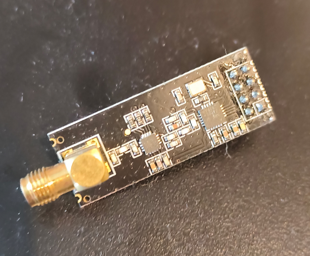
nRF24L01
GF..S.. What?
An antenna can only radiate an electromagnetic wave. If we want to send digital data over the air, we have to somehow encode our 1s and 0s into properties of that wave. This encoding process is called modulation. Different radios encode data in different ways. Some vary the amplitude (OOK/ASK), some vary the phase (PSK), some vary frequency (FSK) and some vary multiple properties at once (QAM).
Probably the simplest modulation you can think of is transmitting a pure sine wave as “1” and turning off the radio for “0”. The frequency of that signal would be called the carrier frequency. You could use a fixed pre-shared baud rate, the radio would tune into the transmitter frequency and detect if the sine wave is being transmitted or not during each symbol. This is called On-off Keying (OOK). This works and it’s wonderfully simple, but the problem is that RF spectrum is a shared resource and this modulation scheme ends up wasting a lot of it, or in other words, it uses a lot of bandwidth considering how much information is being transmitted. You would think a single sine wave effectively uses zero bandwidth, and you’d be right, but perfectly sharp transitions between on and off require infinite bandwidth. Luckily in nature nothing tends to be perfectly sharp or instantaneous, but it’s still a lot of bandwidth. So people have come up with more efficient modulation schemes, that use the shared spectrum more efficiently.
The nRF24L01 chip uses Gaussian Frequency-Shift Keying (GFSK) modulation. First let’s talk about the Frequency-Shift Keying (FSK) part. When OOK used the transmitter being on or off as the “1” and “0”, then FSK transmits a sine wave of one frequency during “1” and a sine wave at another frequency during “0”. The receiver basically detects if the transmitter is sending slightly higher or slightly lower frequency during each symbol. However, transitioning from one frequency to another still causes a sharp transition, wasting bandwidth. To conserve bandwidth, a gaussian filter is used to make the transition between the frequencies smoother.
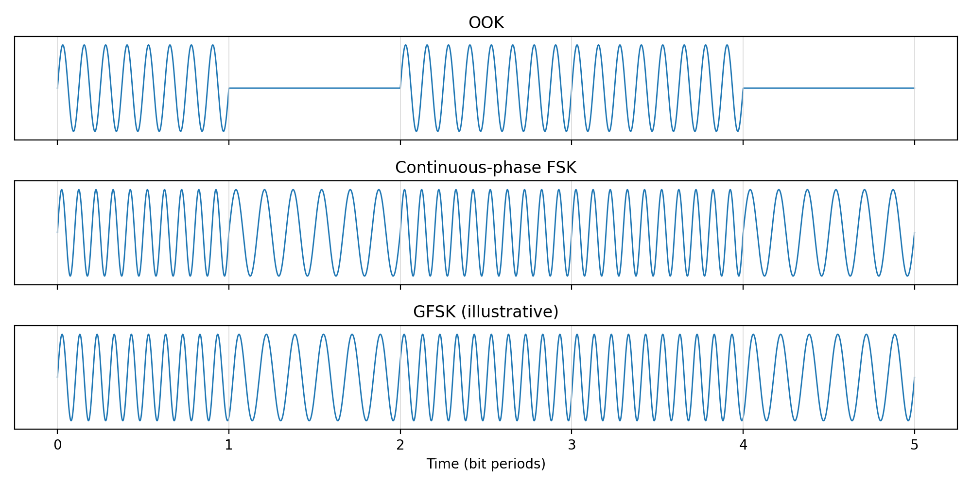
Waveforms of different modulation schemes.
The TX setup
The nRF24L01 module is generally used on small microcontroller boards. Setting up a microcontroller, breadboard and everything else seemed annoying, so I found an easier path. I decided to use USB-to-UART bridge (FT232RL) to bitbang SPI. All I needed was 7 wires and a C program using libftdi. The C program can be found on my GitHub.
The wiring:
| FT232 pin | nRF24L01 pin |
|---|---|
| TXD | MOSI |
| RXD | SCK |
| RTS | CSN |
| CTS | CE |
| DTR | MISO |
The C program sets up the nRF24L01 and then prompts for a message to send. The message can only be up to 32 bytes, which is the maximum FIFO size in nRF24L01. In C code you can also uncomment this line:
nrf_write_reg_multi(0x3, NRF_CMD_FLUSH_TX, NULL, 0);
Which will make the transmitter repeat the same message for 10 ms. This causes continuous transmission around the frequency used by BLE advertising channel 37, so it’s probably better to not do that.
The RX setup
Like I mentioned, I’m using Pluto+ SDR. What I liked about this SDR was the gigabit Ethernet port. The original Pluto SDR is bottlenecked by USB 2.0 speed, so gigabit Ethernet helps achieve higher sample rate. And I can set it up anywhere with an Ethernet cable, a lot less annoying than dragging the box around with an USB cable. Only wish it had USB-C instead of micro USB. It’s not the most modern device out there, but it’s still good value for the price in my opinion.
The firmware that came with Pluto+ did not work as expected. First of all, it refused to work over Ethernet without having the second (data) micro USB cable connected. I checked, data transmission over the Ethernet port worked, but it struggled to hit more than 6 MS/s. None of the builds based on the Pluto+ repo worked well enough. Eventually, I found tezuka_fw repo which has worked flawlessly. However, I needed to open up the Pluto+ case to add a jumper for booting from the SD card.
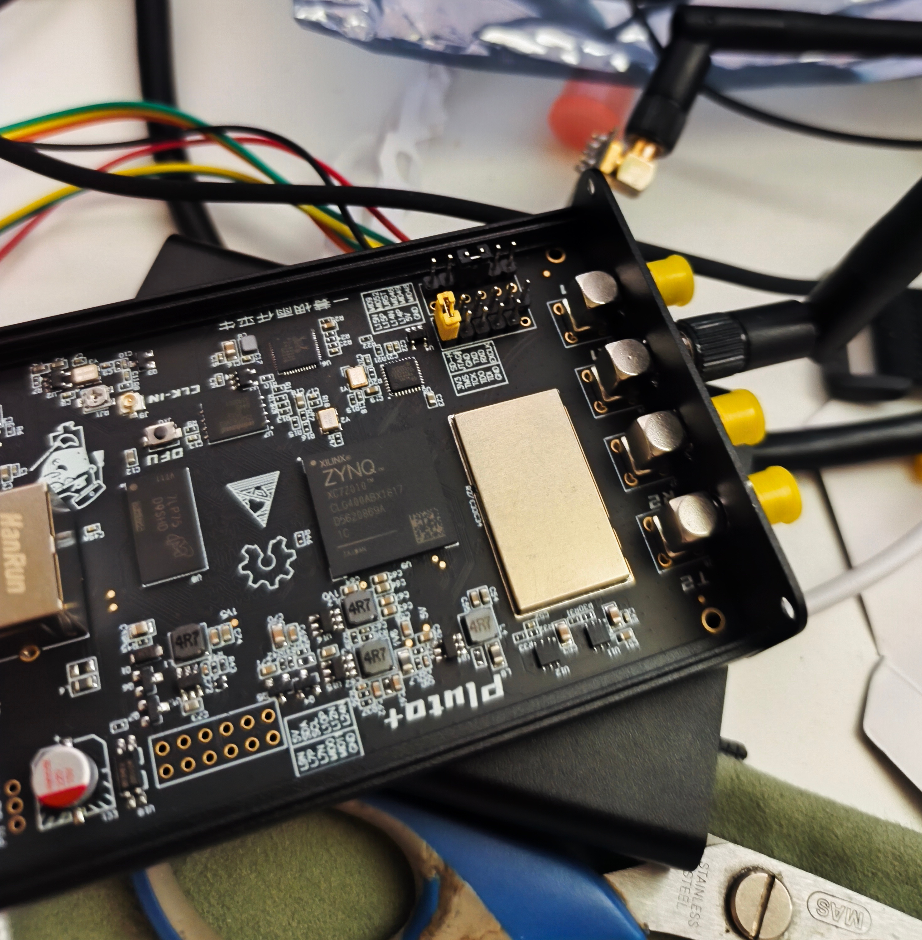
SD card boot jumper.
After switching the firmware, the device itself has worked flawlessly. In SDR++ I had to modify the Pluto source plugin to add “Pluto+” to the whitelist. In GNU Radio it has worked without issues.
Now, all that was left was the “software defined” part of SDR. There are programs like SDR++, which try to provide you with a simple
interface for stuff like listening to radio etc, and there are programs like GNU Radio which only give you the building blocks.
Demodulating nRF24L01 signal isn’t exactly a common desire of users, so it probably doesn’t come as a surprise that we need to build our own radio in GNU Radio.
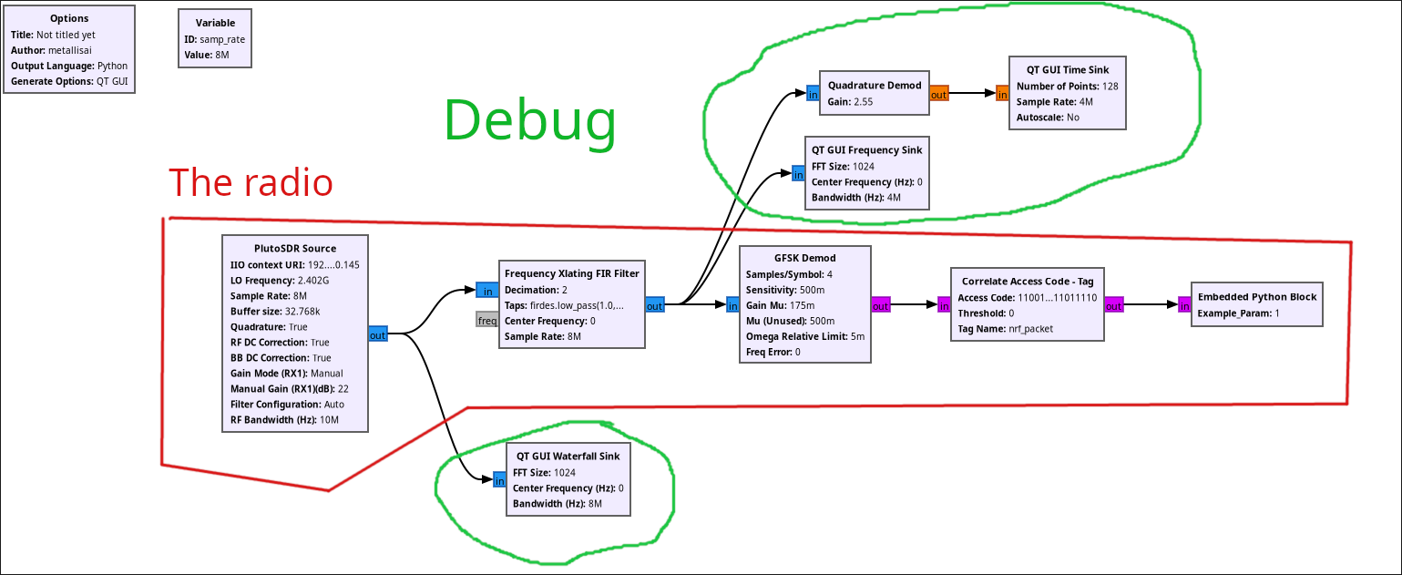
GNU Radio graph.
I have no idea if this is good, I just know it does work sometimes. As I understand it, the “Frequency Xlating FIR filter” removes irrelevant part of the spectrum, then “GFSK demod” block demodulates the signal and finally we just search for the signal in a sea of 1s and 0s. The “Correlate Access Code - Tag” block looks for bit pattern 1100101011101111101111101010110111011110 (which is 0xDEADBEEFCA in reverse byte order, from the TX C source). Then, the embedded python script goes over the tags and parses the packets.
import numpy as np
from gnuradio import gr
import pmt

class NrfParser():
    state = 0 # 0 - idle, 1 - control field, 2 - payload
    cur_bit_idx = 0
    bytes_left = 0
    control_field = 0
    cur_byte = 0
    packet = []
    def __init__(self):
        pass

    def idle(self):
        return self.state == 0

    def begin_packet(self):
        self.state = 1
        self.cur_bit_idx = 0
        self.bytes_left = 0
        self.control_field = 0

    def receive_bit(self, rbit):
        if self.state <= 0:
            pass
        elif self.state == 1:
            self.control_field =  (self.control_field << 1) | rbit
            self.cur_bit_idx += 1
            if self.cur_bit_idx >= 9:
                self.state = 2
                self.bytes_left = self.control_field >> 3
                self.cur_bit_idx = 0
        elif self.state == 2:
            self.cur_byte = (self.cur_byte << 1) | rbit
            self.cur_bit_idx += 1
            if self.cur_bit_idx == 8:
                self.cur_bit_idx = 0
                self.bytes_left -= 1
                self.packet.append(self.cur_byte)
                self.cur_byte = 0
            if self.bytes_left == 0:
                self.state = 0
                self.packet_complete()

    def packet_complete(self):
        s = bytes(self.packet).decode("utf-8")
        print(f"packet complete len: {len(s)}")
        print(f"message: {s}")
        self.packet = []


class blk(gr.sync_block):  # other base classes are basic_block, decim_block, interp_block
    """Embedded Python Block example - a simple multiply const"""

    def __init__(self, example_param=1.0):  # only default arguments here
        """arguments to this function show up as parameters in GRC"""
        gr.sync_block.__init__(
            self,
            name='Embedded Python Block',   # will show up in GRC
            in_sig=[np.uint8],
            out_sig=None
        )
        # if an attribute with the same name as a parameter is found,
        # a callback is registered (properties work, too).
        self.example_param = example_param
        self.parser = NrfParser()

    def work(self, input_items, output_items):
        bits = input_items[0]
        # Find tags in this input window

        cur_idx = 0

        # unfinished packet in progress
        if not self.parser.idle():
            for rbit in bits:
                self.parser.receive_bit(rbit)
                cur_idx += 1
            if self.parser.idle() or cur_idx == len(bits):
                return cur_idx

        tags = self.get_tags_in_window(
            0,                  # input port
            cur_idx,            # first item
            len(bits)           # last item
        )

        for tag in tags:
            key = pmt.symbol_to_string(tag.key)
            if key != "nrf_packet":
                continue
            first = self.nitems_read(0)
            local_idx = tag.offset - first
            cur_idx = local_idx
            self.parser.begin_packet()
            for rbit in bits[local_idx:]:
                self.parser.receive_bit(rbit)
                cur_idx += 1
                if self.parser.idle():
                    return cur_idx
            break
        return len(bits)
The NrfParser class is a state machine to parse the packet. The work() function goes over the tags in the current bit array, and starts parsing a new packet when it finds a “nrf_packet” tag.
The tag name was specified in the “Correlate Access Code” block.
I was only interested in the demodulation part, so it’s very minimal. For example, I assume there is no CRC and everything except packet length is hardcoded.
Results
Here is my setup. The SDR antenna is mounted on the window 0,5 m away.
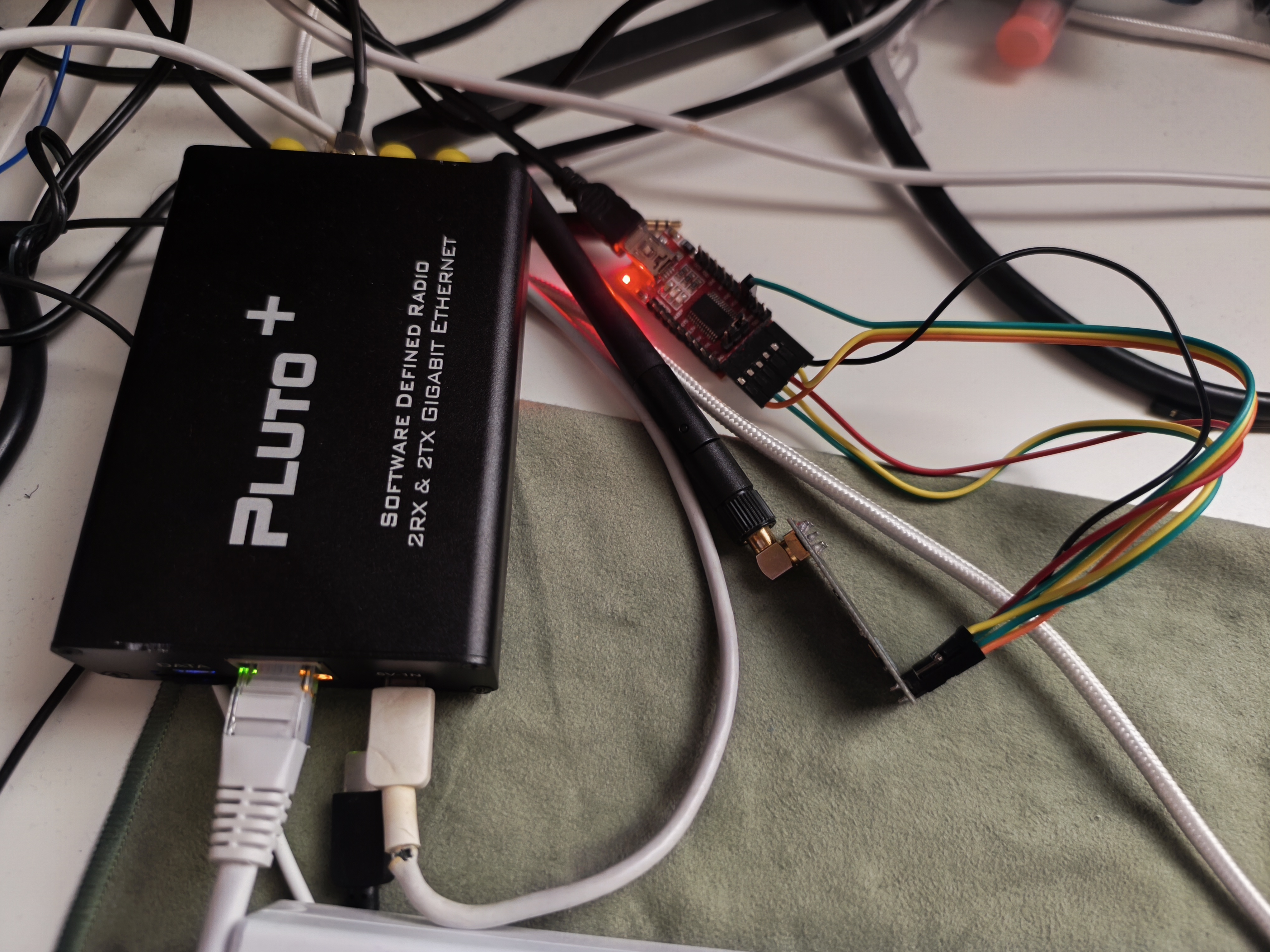
The setup.
The signal sent by the nRF24L01 wirelessly reaches my SDR:
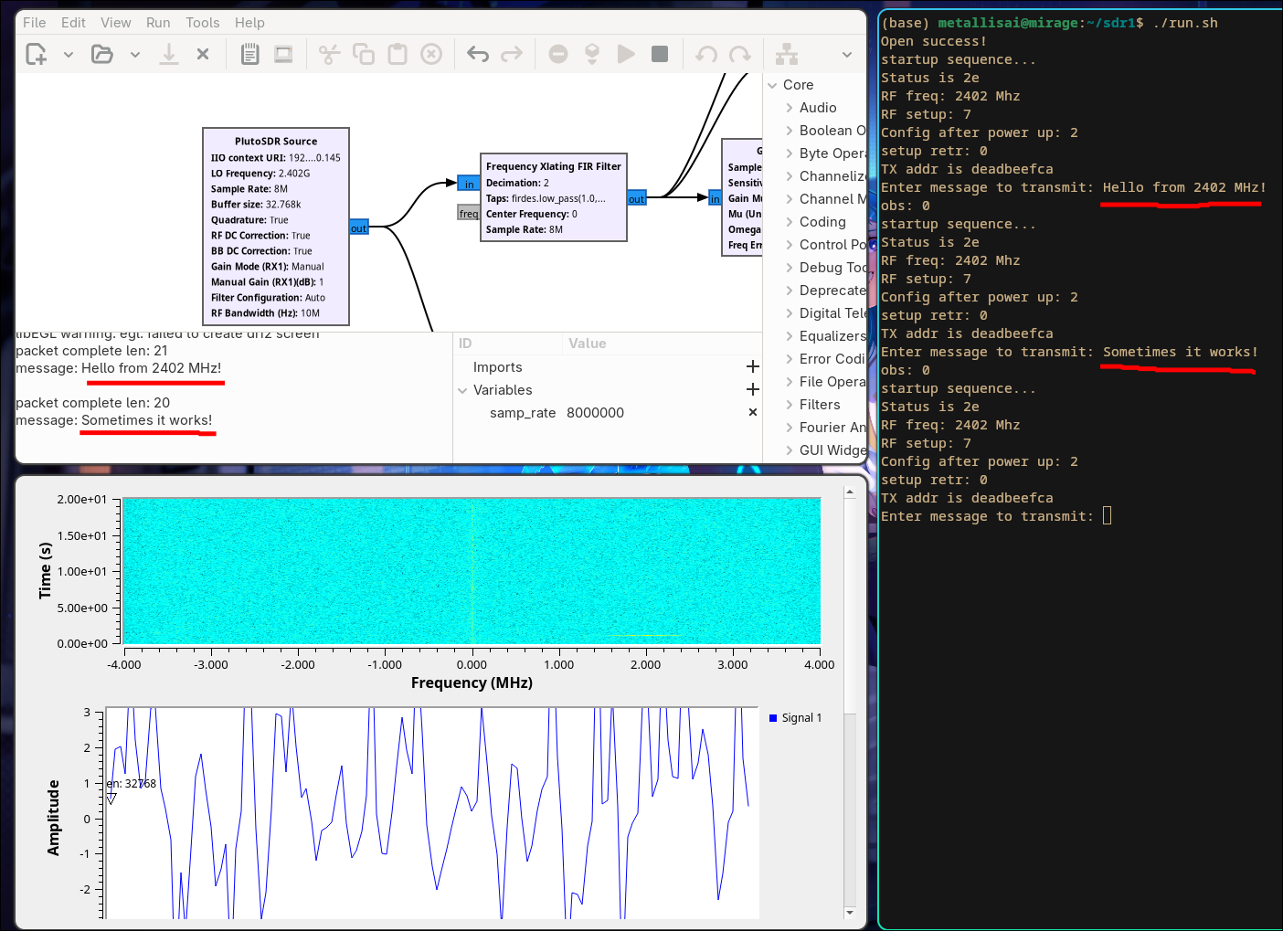
The result.
Sometimes the message isn’t detected, so this leads me to think something is still off. The transmitter and receiver are right next to each other, so the receiver should always hear it. It could be that the transmitter is overloading the receiver since it’s so close, reducing the gain to 1 made it more reliable.
Overall, it was a great learning experience and I’m happy with the result. Eventually, I’d like to build my own radios based on the AD9363 or similar chip and and an FPGA, but there’s a lot more to learn before I’d even try. Also, I don’t have a clear application in mind, so it’s a bit tough to find motivation.