How it came to be
As a part of my bachelor’s thesis I had to modify a motor ESC schematics. Due to electronics component shortage in recent years it is very hard to get a lot of parts. It was for automotive use, so it was nearly impossible to find the parts needed in time. Thus I had to drop the hopes of ever assemblying that board.
It was the first electronics board I had ever designed and it felt bad that I could never see my design put into practice. So I designed a new one from scratch using cheap parts that are available. Initially I started off in Altium Designer but eventually ended up moving to KiCad 6. The design is 4 layers and manufactured with JLCPCB’s standard 4 layer options. I sourced all parts from LCSC (JLCPCB’s sister company) for convenience and since this is mostly for learning purposes I don’t mind the cheap parts.
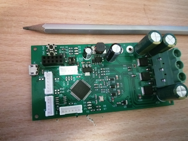
The final board
The design ended up being 100x50mm. Schematic can be found here.
ESC front
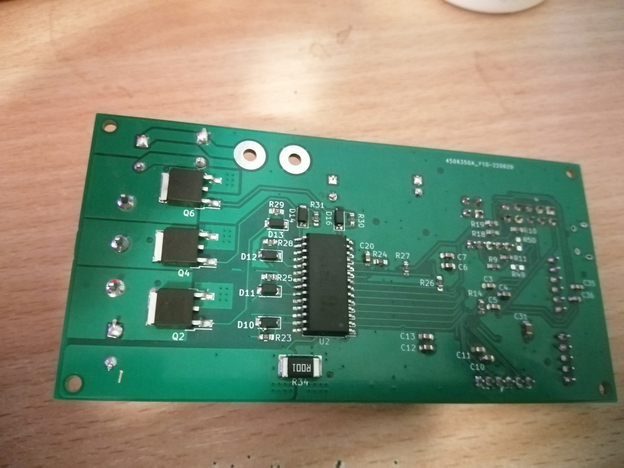
ESC back
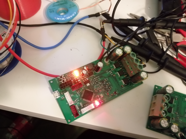
ESC working
The parts only cost about 10€ per board, most expensive being the MCU at 2.5€. I used IR2136 to drive the 6 NMOS, namely EG2136 and SLM2136 (both worked interchangeably). IR2136 has somewhat bad reputation based on what I’ve seen online. I was quite careful to avoid unneccesarily fast switching transients and it has worked without issues for me. Keep in mind its an old chip, I used it only because its cheap.
It can work at about 10-20V, so its good for 3-5S LiPo. I think it can take about 30A, but I haven done the math or tests. The limitation on voltage is the FET gate driver IC and the current shunt amplifier (used to measure current). The driver part could easily be changed to handle up to hundreds of volts, but current shunt amplifiers only go up to 60V with a reasonable price. The only alternative that I know of is using a Hall-effect current sensor, its expensive but at that point the sky is the limit. I wasn’t interested in sensorless FOC, so measuring current isn’t that important for this design, I only do it for overcurrent protection.
The software
I wanted to try and write basic software for the board. The board supports 3-phase motor with either binary Hall-effect sensors (6-step square wave) or FOC with an encoder. The options for encoder are SPI, I2C or sine-cosine encoder. For the first version I’ve gone for sine-cosine encoder and I’m not sure if it was a good choice. I also left an option for a single CAN bus and micro-USB for IO.
Right now I have Infineon’s TLE5109A16 E2210 chip as the encoder. Basically you’d use a diametrically magnetised magnet on the rotor and the sensor would give you cosine and sine of the angle as output voltage. It is best to use differential signalling so you’ll end up needing 4 ADC channels to measure it with a MCU. To get the angle you’d use atan2 function on the measured voltages. The great part is that the magnitude doesn’t matter at all as long as the distortion is same for both signals.

Diametrically magnetized magnets
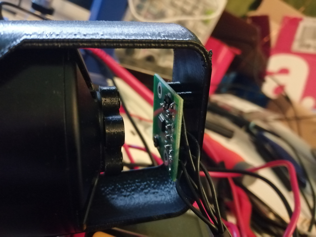
Encoder on outrunner BLDC motor
Pretty much all BLDC motors have multiple pole pairs. The outrunner motor I have has 14 magnets, so it must have 7 pole pairs. In conclusion there is multiple elecrical revolutions per single motor revolution. Basically you have to divide motor angle by number of pole pairs. Unfortunately this isn’t all. You have to also know the offset between electrical angle and motor angle, unless you somehow align them physically. BLDC motors are synchronous, so you can use forced commutation to get the motor to a known electrical angle. From there you can measure the offset. Due to friction and other inaccuracies you’d probably want to take a more statistical approach if you intend to measure the offset in software, doing multiple turns different directions etc.
I’m not that sure anymore if using sine-cosine with just a MCU is great choice. The motor I’m using has 7 pole pairs, which means the electrical RPM is 7 times higher than actual RPM. This means that even at 3000 RPM you’re gonna need to sample the sensor at several hundred khz. That’s pretty bad considering you have to calculate atan2 every time. Using a LUT is tough also, because atan2 has 2 input variables.
What about commutation? How do you get a sinusoid with 6 MOSFETs? The short answer is that you don’t, you use a PWM waveform that averages to the signal you want. If you’re not familiar with motor commutation, but have worked with MCUs before you might be thinking of sinusoidal PWM (SPWM), but thats almost never used for motors. The common 3-phase BLDC motors that you’d find in skateboards and other stuff are wired in delta configuration. This means you don’t really have control over individual phases - to shoot current through one phase you have to create a voltage difference with another phase and current will pass both of them. If you simply use 3 phase shifted SPWM signals you’re only gonna get current through the motor if at least 2 phases have a voltage difference not whenever the phase is high. It might spin the motor, but its far from optimal.
Instead of SPWM you’d want Space Vector Modulation (SVM). Note that SVM has multiple possible waveforms, I won’t go into details because I haven’t fully worked through it either. I just use the algorithm thats been already developed. I found Infineon’s paper useful to implement it.
Video shows SVM with forced commutation with speed ramp. Don’t mind the smoke, I used breadboard wires which couldn’t handle the current.
Wrap up
Overall I’d call this project a success as a learning experience. I’m happy with the results considering its my first board. I’m not quite sure what I’m gonna do with this yet, but I have some ideas.